Handwired Keyboard Build Log - Part 1
Update 1: I’ve finished the second part of the serie
Update 2: The plate I’m using has a height of 1.5mm, not 2.5mm as some astute readers have pointed out.
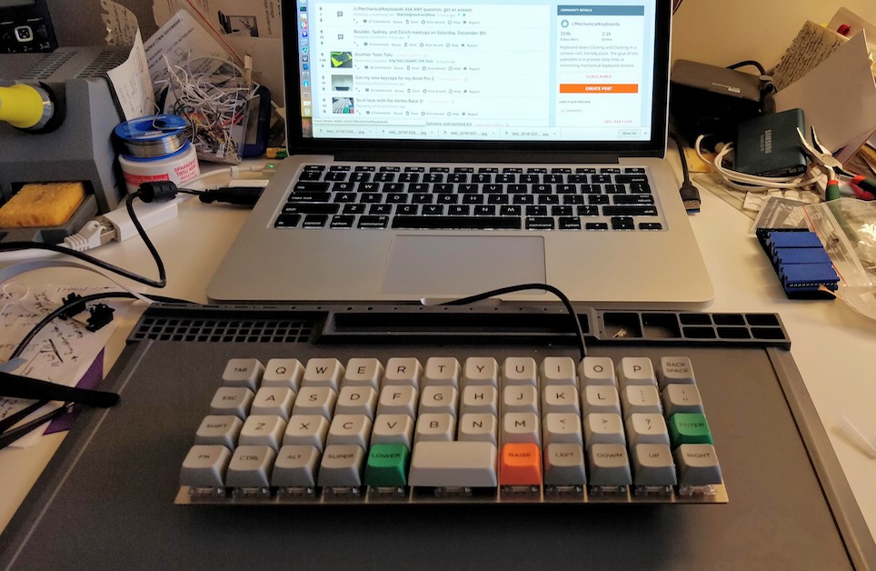
For the last 7 months, I’ve been discovering a new hobby: DIY mechanical keyboards. I’ve been using mechanical keyboards for ages (I was mostly typing on a Code keyboards lately), but lately moved to type only on my macbook keyboard (hopefully this is an early 2015, so the keyboard ie bearable).
So 7 months ago, I was browsing the Internet when I discovered a new world: there were passionate people that are building their keyboards and even programming them with QMK.
I soon was embarked in a no return journey to find the perfect keyboard, made of custom keyboards purchased from Korean Group Buys, properly prepared keyboard switches, custom color keycaps, split backspace layouts…
Forward to a month ago, I discovered that some people were building their own keyboards without any PCB, I then decided to try following the best handwiring guide with one of the smallest existing keyboard.
This serie of posts is the story behind this keyboard:
What’s a keyboard anyway
A keyboard if the combination of the following elements:
- a matrix of switches soldered to a PCB
- a metal or aluminium plate on which the switches are clipsed to
- a controller that “reads” the matrix and sends keycodes to the USB port
- keycaps
So in a very fast loop, the controller’s firmware will power on one column of the matrix and “read” the tension back on the matrix rows. If there’s some tension on one row given current on a column, then the controller can deduce which switch has been pressed. The firmware will then send the corresponding keycode based on the layout to the USB port, and continue with the next column and so on infinitely.
But there’s a problem: if one presses more than one key at a time, it is possible for the controller to register ghost keypresses. See the following schema:
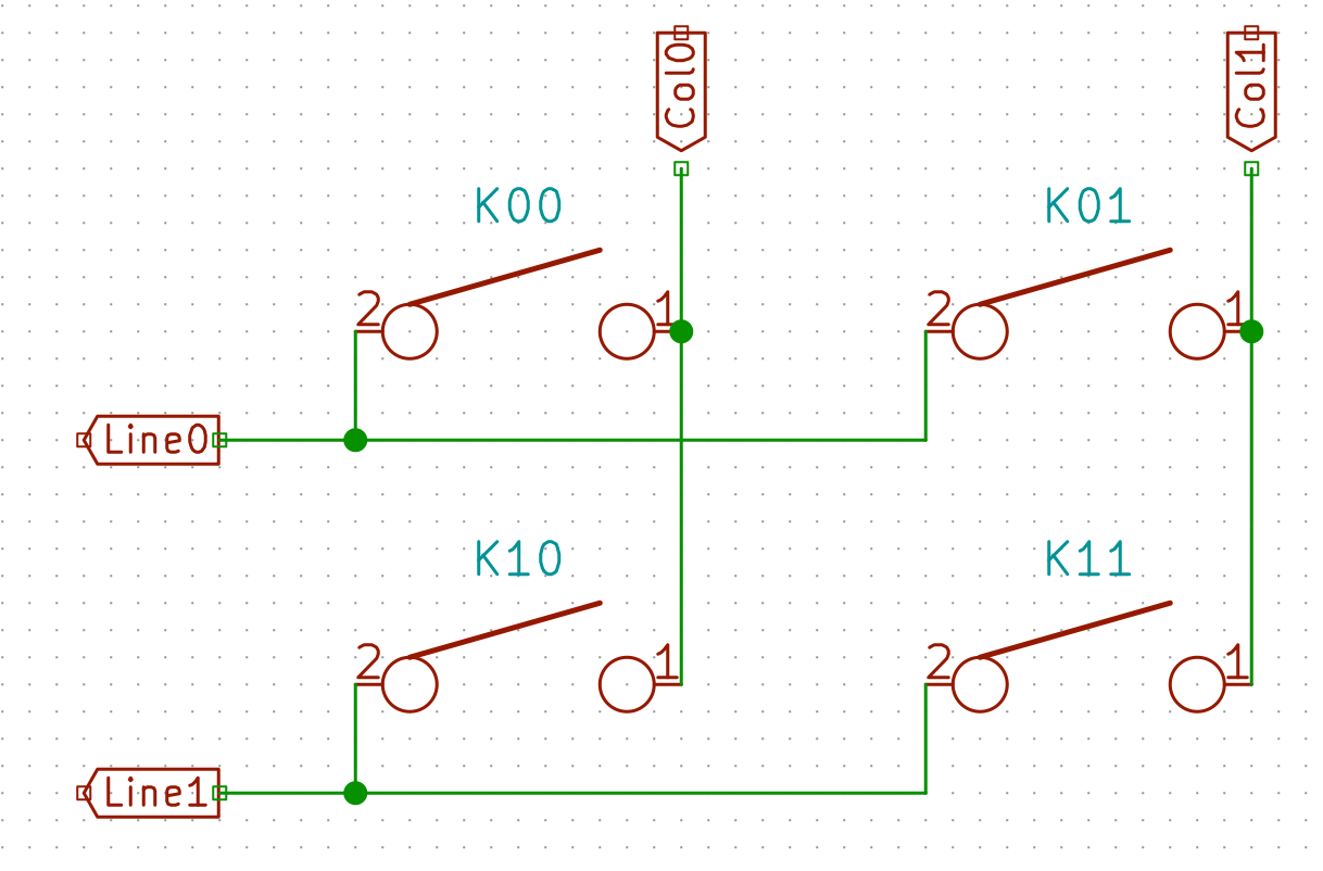
When the controller will power the Col0, and if K00, K01 and K11 are depressed simultaneously, the controller will read current on both Line0 and Line1, because the current will flow from Col0 to K00 pin 1, then pin 2 because the switch is depressed, then to switch K01, then to switch K11, then to Line1. For the controller it is as if all the switches have been pressed, instead of the 3 that were indeed depressed.
To prevent this we add diodes between the switch and the row it is connected to:
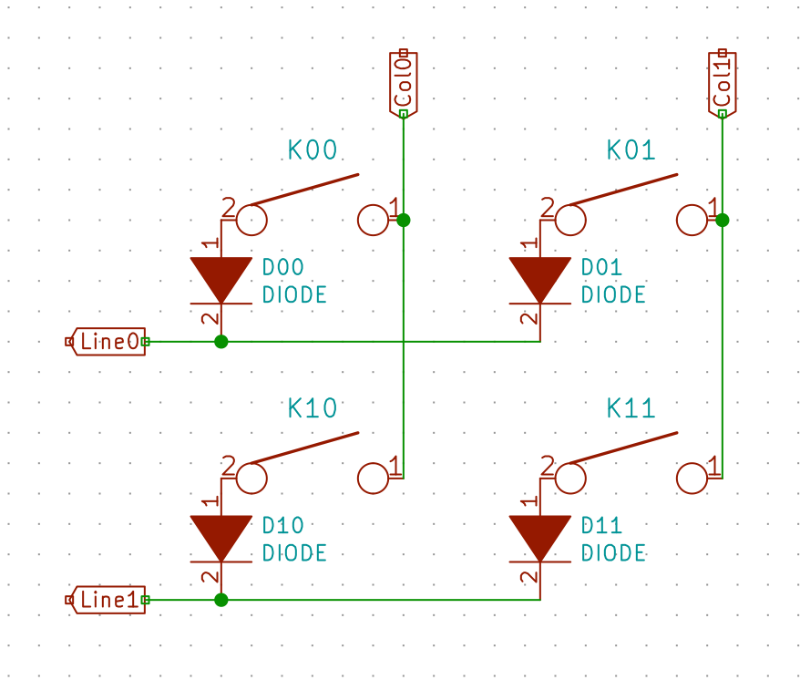
In the same hypothetical scenario as before, the current will be prevented to flow back from K00 to K01 and from Line0 by the D01 diode. Thus when powering Col0, the controller will only see a tension on Line0. And when powering Col1 it will see a tension from Line0 and Line1, thus registering 3 key presses.
Handwiring
Handwiring as its name implies is an electronic technique of building electronic circuits without using a PCB, and instead wiring all components one by one manually with small electric wires. It is often used to perform prototype of electronic boards.
The aim of this build log is to show how to wire a fully working (but small) keyboard.
The BOM
We’re going to build a Planck like keyboard in MIT layout, that is a matrix of 4x12, with a 2u spacebar, accounting for 47 keys. I chose this keyboard and layout because it’s one of the smaller keyboard (a 40%) and it is ortholinear (all switches are aligned) making it easy to wire.
So what will we need to build our keyboard:
- 47 switches. I had a left-over of Aliaz silent 70g switches
- a planck plate (which I purchased pre-made by Laserboost). You can get one either from them or Lasergist if you send them the CAD files. You can easily get the CAD files from the KLE layout tool and swillkb. I choose a 1.5mm metal plate to make sure it is sturdy enough to type on it.
- electric wire of 0.2mm2 (24 AWG) of different colors
- 47 diodes 1N4148
- a controller: teensy 2.0. It can be a Pro Micro or even the newer QMK Proton C.
- around 30cm of 24 way 1.27mm pitch ribbon cable
- a ribbon DIP connector to attach to the ribbon cable and solder the teensy
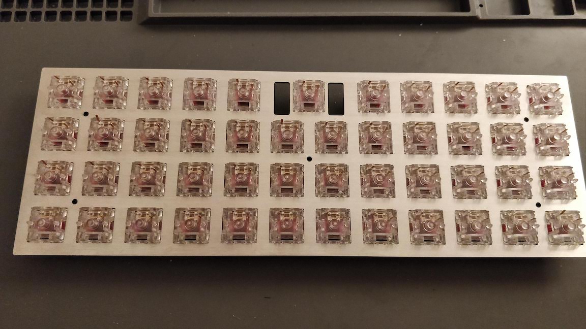
The MIT layout Planck plate looks like this:
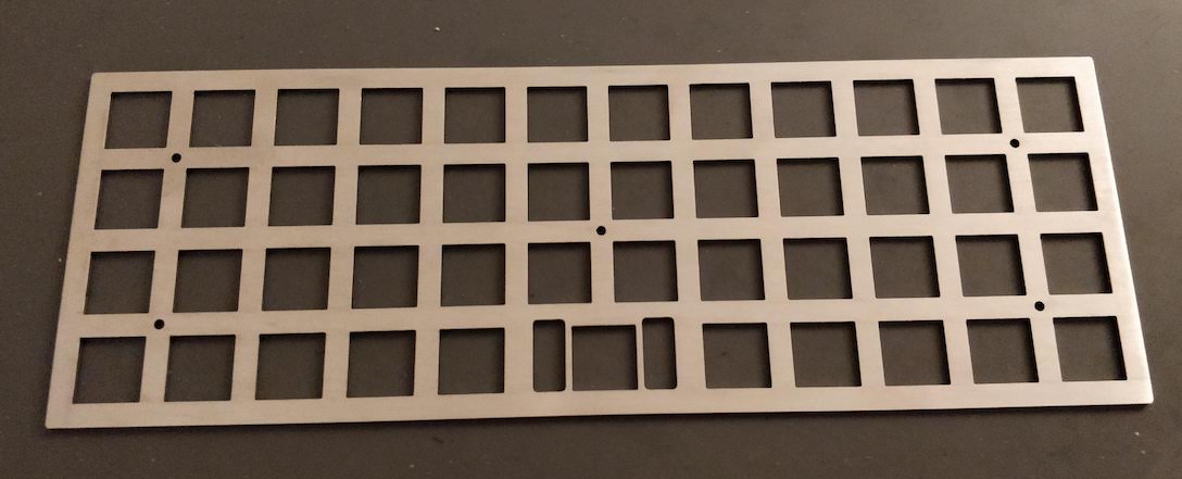
Note that this plate has holes for a PCB mount stabilizer for the 2u space bar. I should have taken a version for a plate mount stabilizer, because with a PCB we won’t be able to put a stabilizer under the space bar.
We’ll also need the following tools:
- a wire stripper. Being in Europe I got myself a nice Stanley one.
- a set of tweezers
- a precision wire cutter
- a multimeter with continuity mode
- a soldering station (preferrably temperature controlled) and solder
- a sharp knife or razor (to remove insulators on very small cables)
- an usb A to usb mini cable for programming the controller
The most important part is the insulator stripper:
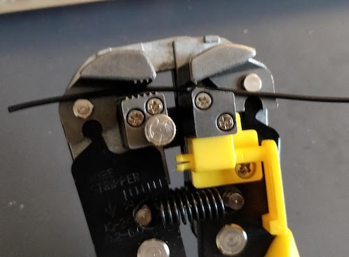
You can get a Vise Grip or any other tool like this one. You might need to tune it’s strength (there’s usually a small knob on the tool) so that it doesn’t cut the small wires.
In this part of the story, we’ll only need the wire stripper, some colored wires, the plate, 47 switches, tweezers, a multimeter, the wire cutter, solder and the soldering station.
Placing the switches
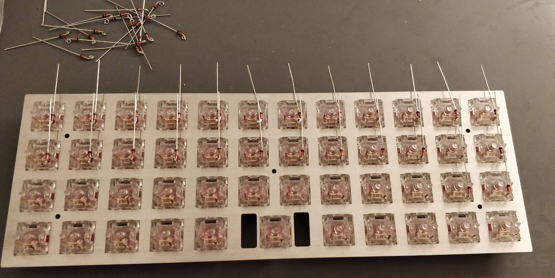
The very first step of our handwiring work is to firmly clips the switches on the plate:
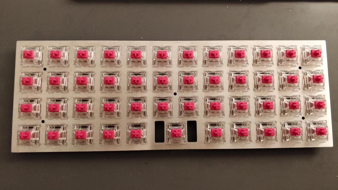
I put the switches facing north (the led hole is at the top) so that the higher pins when seen from the back of the plate will be the pin connected to the rows, and the other one will be connected to the columns.
With a 2.5mm plate, the switches should clipse correctly on it. Make sure the plate is using MX switch holes without “top-opening” punches (straight square holes).
Preparing the diodes
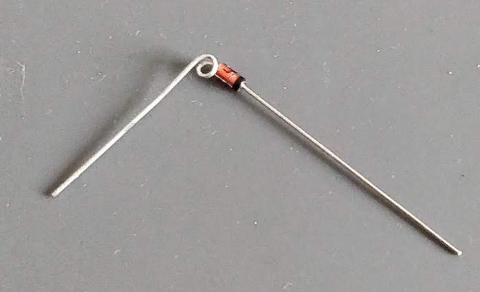
We’ll have to solder the diodes on the switch pin connected to a row. Since there’s no circuit copper pads to put the solder on like on a PCB, the best way to solder something on a pin is to form a small wire loop and put solder on it. The solder will “flow” between the pin and the loop and stick firmly.
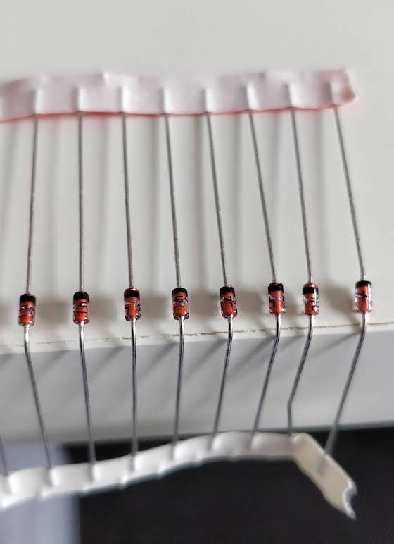
So our first task is to form a small loop with one of the leg of the diodes. Make sure to do it on the correct leg: the one opposite to the diode black mark:
To ease the process and especially if you got your diodes in bands, you can bend them all in one shot on your desk table like this:
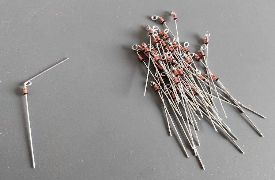
Next, remove the diodes from the strip, and using a tweezer block the wire in it and form a loop by turning around the diode leg. With the tweezer you can make sure the loop is flat. Make sure the loop is big enough to be placed on a switch pin, if not open it a little bit with the tweezers.
Repeat this for the other 46 diodes.
After this you can cut the extraneous diode leg just after the loop:
Soldering the diodes
The very next step is to place the diode loops on each of the switch row pins:
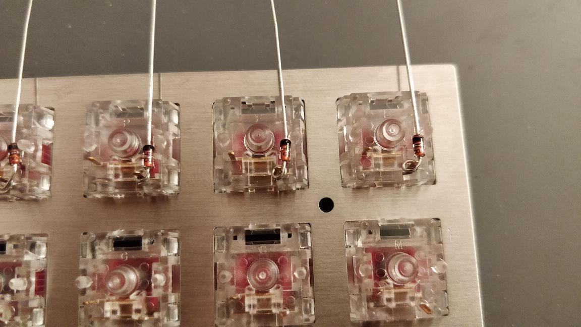
And then soldering them:
Make sure to orient correctly the diodes and leave the other leg correctly aligned.
Notice that I started placing and soldering the diodes from the top row (as seen from the back) so that the other rows diodes long legs doesn’t hinder soldering the next row.
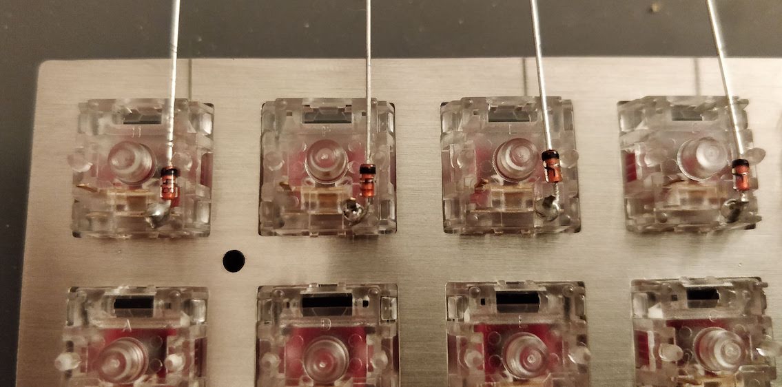
We’ll then keep adding diodes and soldering them until we’ve covered all switches:
It is important to not cut the remaining leg yet. We’ll use it to connect to the row wire as you’ll find in the next step.
Building the rows
To build the rows, we’ll take a long piece of wire (I used black wire). The first thing to do is to remove the insulator at the loose end on something like 5cm with the wire stripper.
We know that we have 12 switches on a row (except the bottom one which has only 11 switches). There is 19mm between two switches.
Instead of cutting 11 pieces of wire which will be hard to solder in place correctly, we’ll use only one long straight piece of wire on which we’ll split the insulator with the wire stripper into 11 pieces of around 16mm each (without cutting the cable). Since it is hard to correctly measure the insulator length while using the wire stripper, I used a visual clue on the wire stripper to approximate the correct length and aligned the insulator pieces with it before cutting.
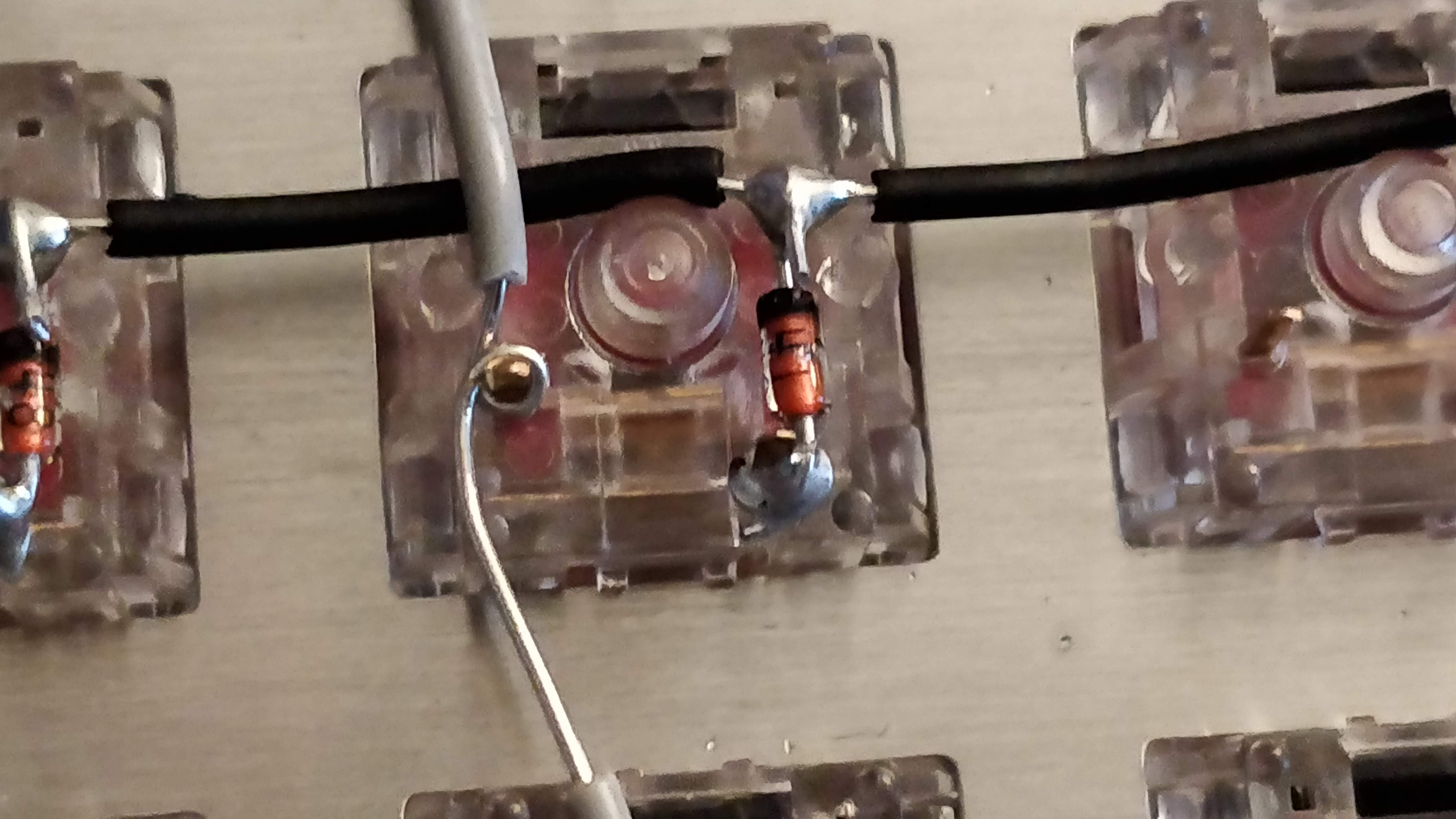
To solder the wire, we’re going to bend the diode leg around the cable to form a half loop and solder between the insulator pieces. At the same time secure the row wire with the switch central bumps.
We’ll start by soldering the loose end on the first diode, then proceed to the next diode: push the insulator piece toward the first junction, solder and move back the insulator at equal distance:
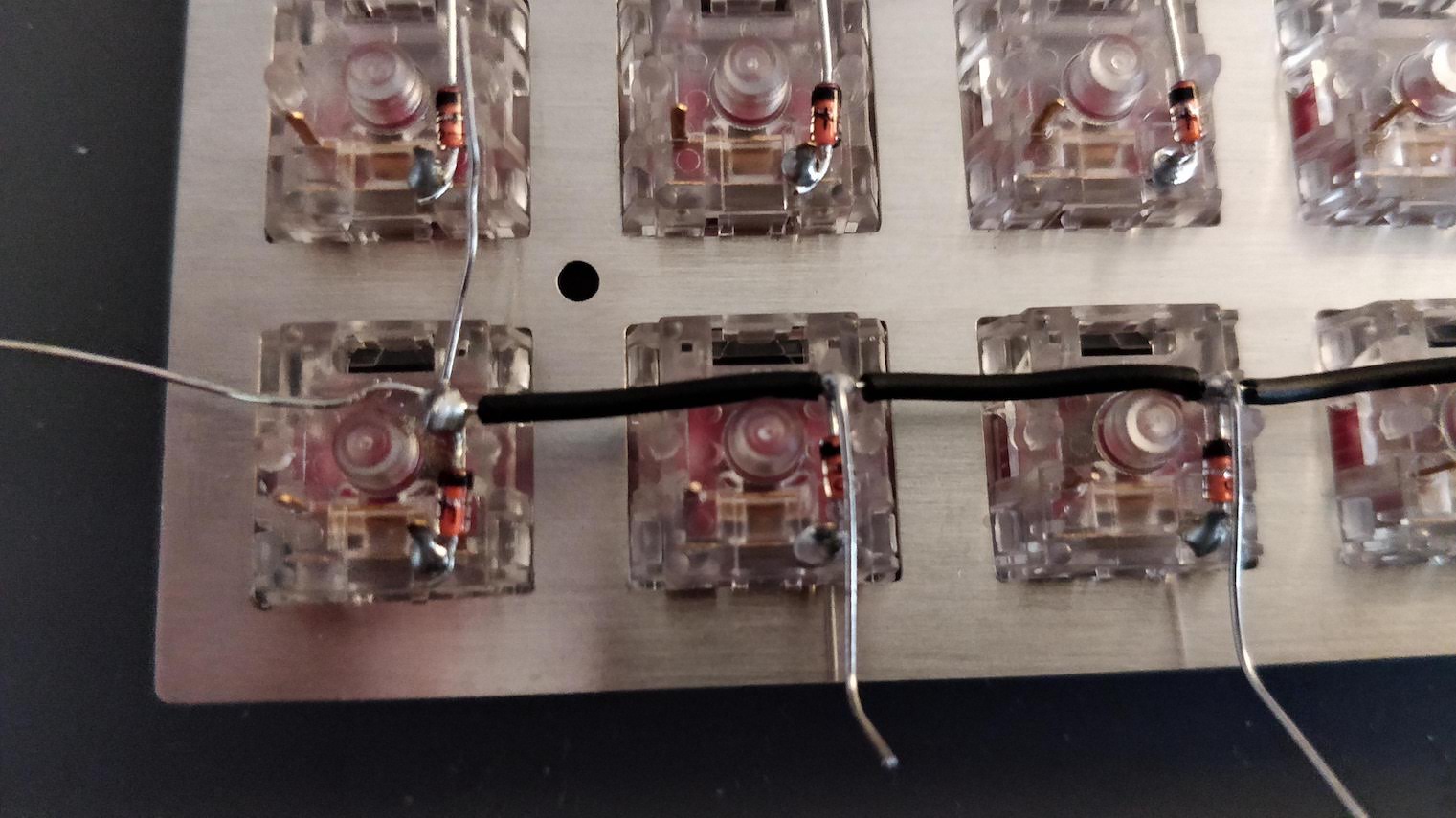
For the first diode, I formed a complete loop with the leg around the wire. For the subsequent diode since it is not practical to do that, I’ve done only half loops.
Another option which I used at first is to cut the insulator with the wire stripper on each step instead of cutting the 11 pieces at once. So solder one diode leg, cut the insulator at the right lenght, push it toward the last soldered diode, solder the next one, and so on. This is more effective if the distance between switches is variable, otherwise use the first method.
The last diode in the row should also be soldered by forming a full loop with the diode leg around the wire.
It is important to solder the diode leg on the wire before moving to the next diode leg along the row, otherwise the cable could move during the process and nothing would be correctly aligned.
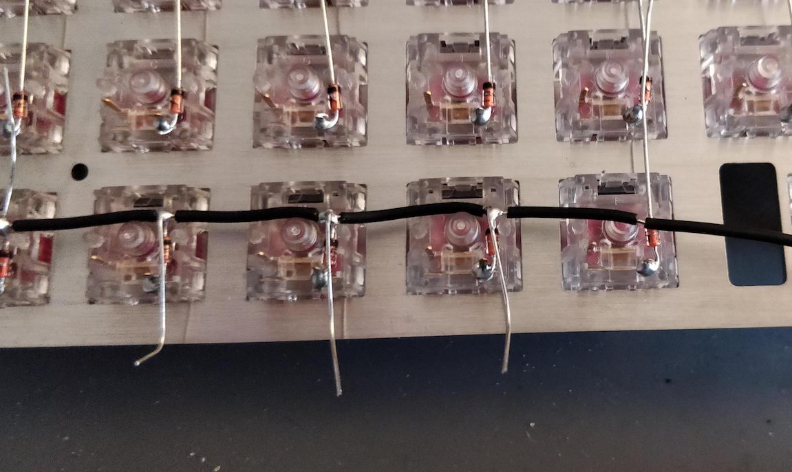
Cut the extraneous wire at both ends and all the remaining legs with the wire cutter and you should obtain something like this:
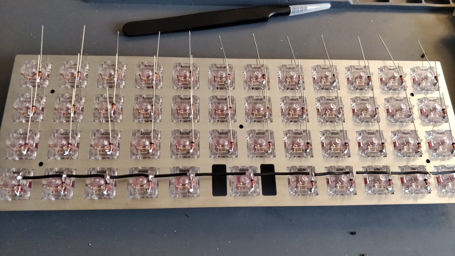
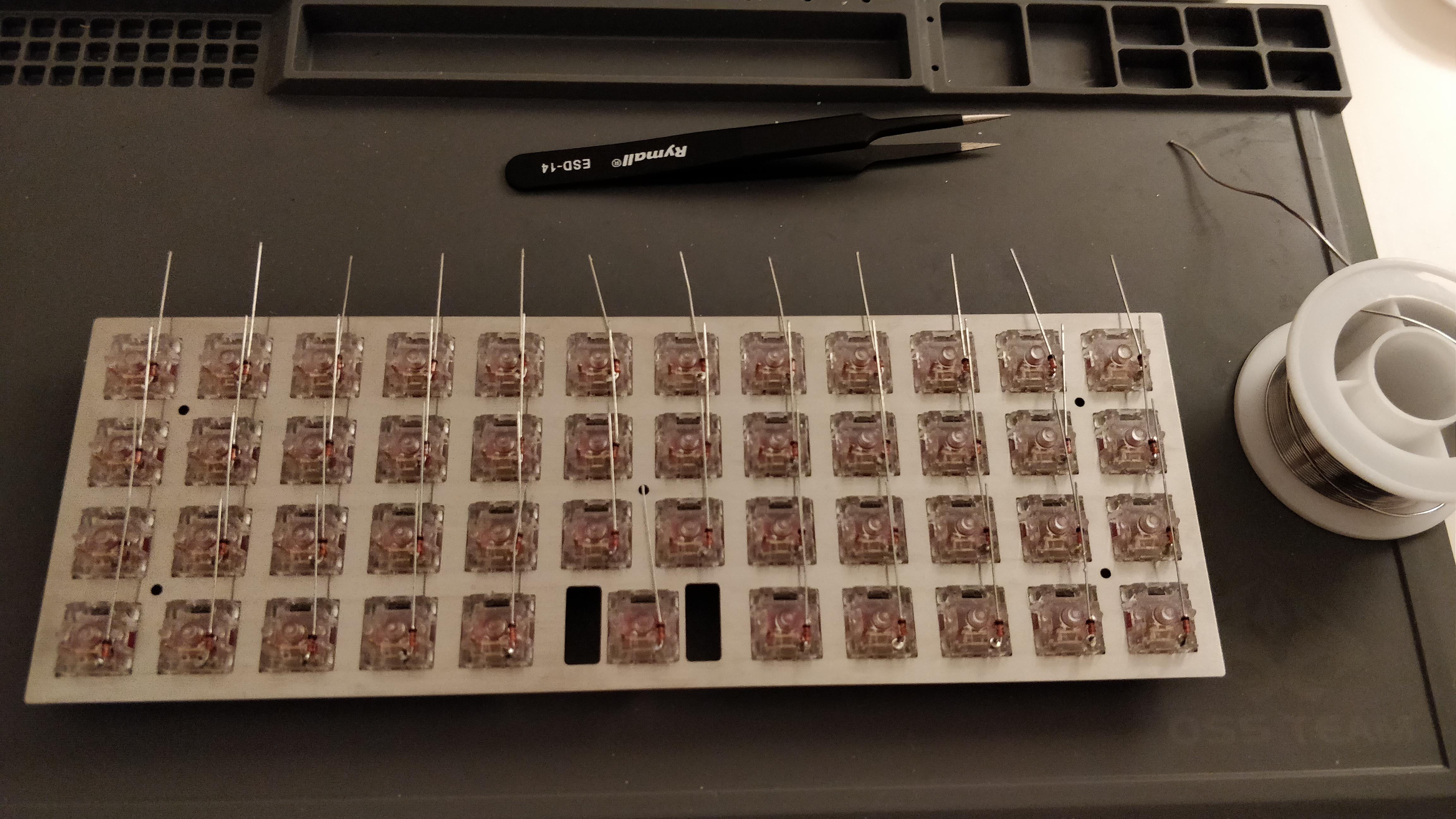
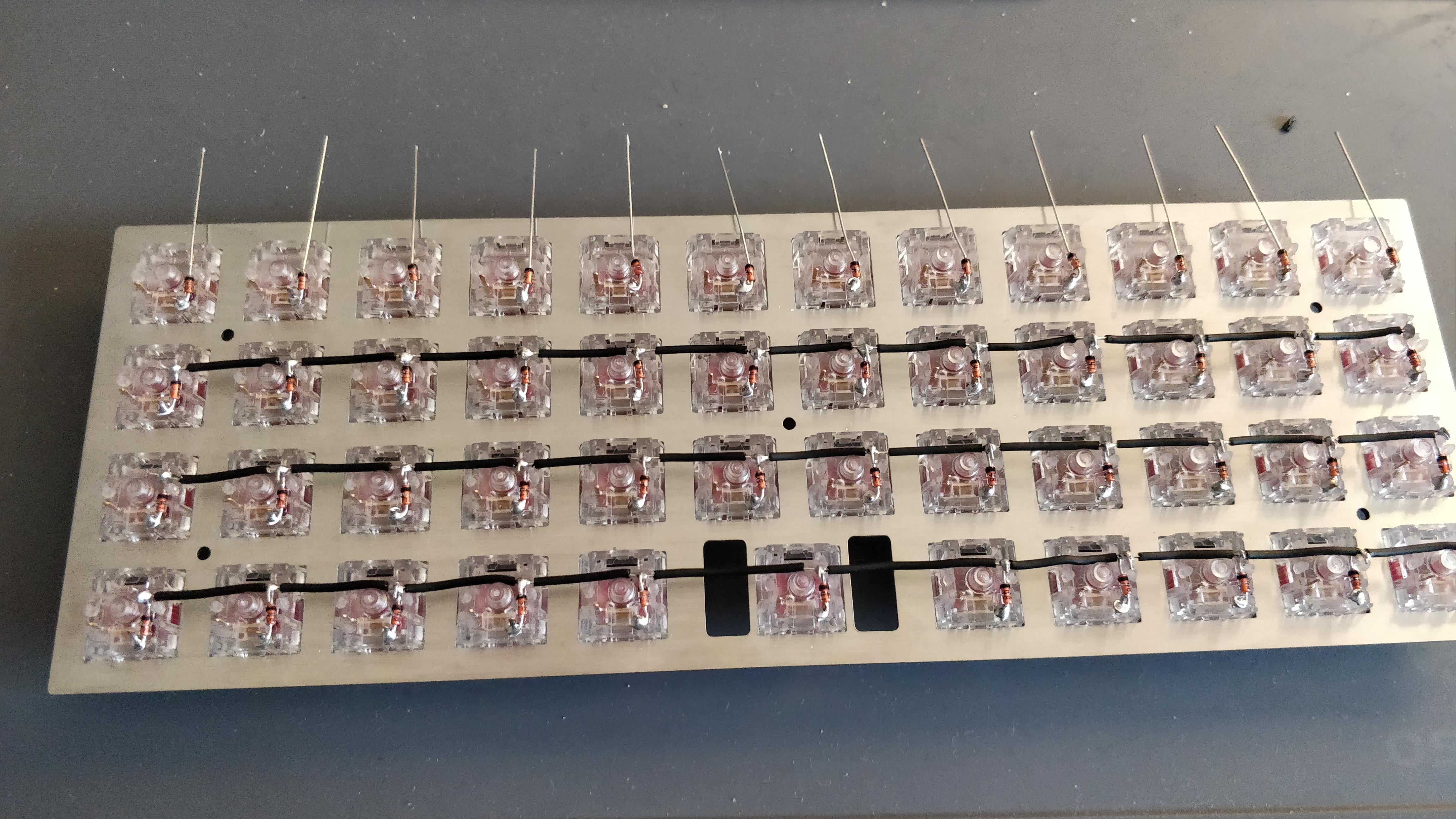
Apply the same technique to the 3 remaining rows. It takes around 10 minutes to solder a 12 switches row:
At this stage, you can check with a multimeter that each switch is correctly connected to the wire. Use the multimeter in continuity mode (the multimeter will beep if there is continuity between two junctions), and put the black electrode on one row end and place the red one on every diode junction, there should be a beep. You can also test the continuity of the switches and diodes combination: still with the black electrode on the row, place the red one on the other switch pin and press the switch: the multimeter should beep.
Once you’ve made sure everything works electrically, it is time to move to the columns wiring.
Wiring the columns
For a better visual effect, I’ve decided to wire each column with a different wire color. Unfortunately I couldn’t find 12 different wire colors, so I’ve used only 6 that I repeated twice. I arranged the colors in an approximation of a rainbow.
We’ll use the exact same technique as for the rows, except that we need to split the insulator into only 3 pieces of equal length (there are only 4 rows on this keyboard). To make sure we have enough wire, I didn’t cut it before soldering the last switch in a column.
Since we don’t have the diodes leg to form a loop around the wire, we’ll build loops with the wire around the switch pins:
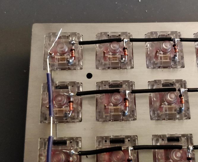
Once soldered we can move to the next switch, push back the insulator toward the previous switch, solder the current one and so on:
Keep doing this until you’ve done all columns. It takes only a few minute per columns once we get the habit.
Since there are only 11 switches on the bottom row, one of the column will span only 3 switches.
The result should look like this:
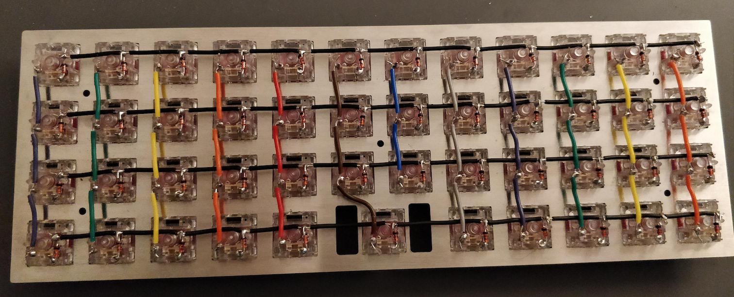
You can then use the multimeter to check the colums are correctly wired, and that no rows is electrically connected to a column.
What’s coming next
In the handwired build log part 2, I’ll explain how to connect the controller to the matrix and how to program the controller to become a working keyboard. We’ll also put some keycaps on.
Another part will explain how I’m going to build a bottom plate for the keyboard.
Comments