Handwired Keyboard Build Log - Part 2
In the handwired build log part 1 we saw a technique to build a nice keyboard matrix without using a PCB.
In this part we’ll discover how to hook the teensy controller to the matrix.
The needed tools & parts
For this part, we’ll use:
- the soldering station and solder
- a pair of tweezers
- a sharp knife
- a wrench
- a philips screwdriver
We’ll also need those parts:
- a ribbon cable DIP connector
- 5x 1.8mm PCB spacer
- 10x M2 screws
- about 30cm of 24 way ribbon cable
- the teensy 2.0 controller
Preamble
We plan to put the controller on a ribbon cable DIP connector:
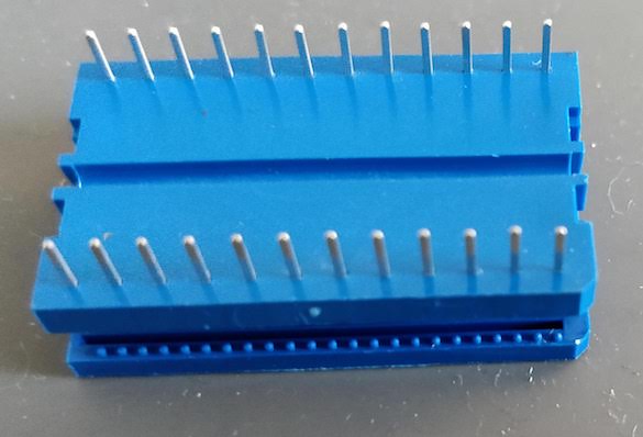
This is a special connector normally used to solder a ribbon cable to a PCB. This connector has the same footprint as a teensy, so instead of soldering it to a PCB, we’ll solder the teensy on the connector.
The ribbon cable will go from this connector to the matrix. To secure the ribbon cable, we need to use some wrench to crimp the connector on the ribbon cable. Each conductor from the ribbon cable ends up on a pin of the DIP connector:
For the controller to read the matrix we need to wire each row and each column to a given port on the MCU. The good thing is that any port will do it, we don’t need to wire specifically a column or a row to a specific port (this would have been different if we had backlight leds which work better with a PWM capable pin).
An upcoming case?
I didn’t plan any case, but I want in the end to put a transparent PMMA bottom on which I could glue the controller. Since the plate has 5 M2 screw holes, I plan to secure the bottom plate through these holes by using the screws and five PCB brass spacers.
Wiring the matrix to the controller
We have 12 columns and 4 rows in the matrix, all those needs to be connected to the MCU ports. That means we’re going to use 16 conductors out of 24 on our ribbon cable.
For aesthetic reasons, and since 12 is a multiple of 4, I’ve splitted the 16 conductors ribbon cable in 4 pieces of 4 conductors.
The idea is to route the 4 conductors ribbon up to where the individual connector will be soldered to the matrix.
The big difficulty is to plan the length of the 4 conductors ribbons and when to split them in individual conductors. Again for aesthetic reasons, I decided to keep the conductors bound together in the ribbon as much as physically possible.
The other good news is that a small ribbon of 4 conductors is about the same size as the distnce between 2 switches. So I can route those ribbons easily under the matrix wires and between the switches up to their respective destinations.
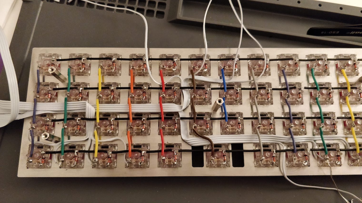
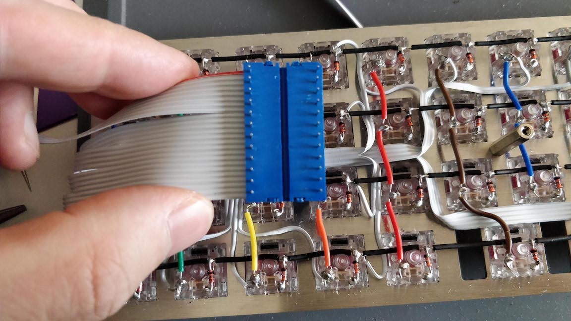
For aesthetic reason again, I decided to route all the ribbons starting from the controller at the same place in the back of the board, and make some 90º turns when needed. So I need to route them sorted by length (ie start by routing the longest ribbon and finish by the smallest one).
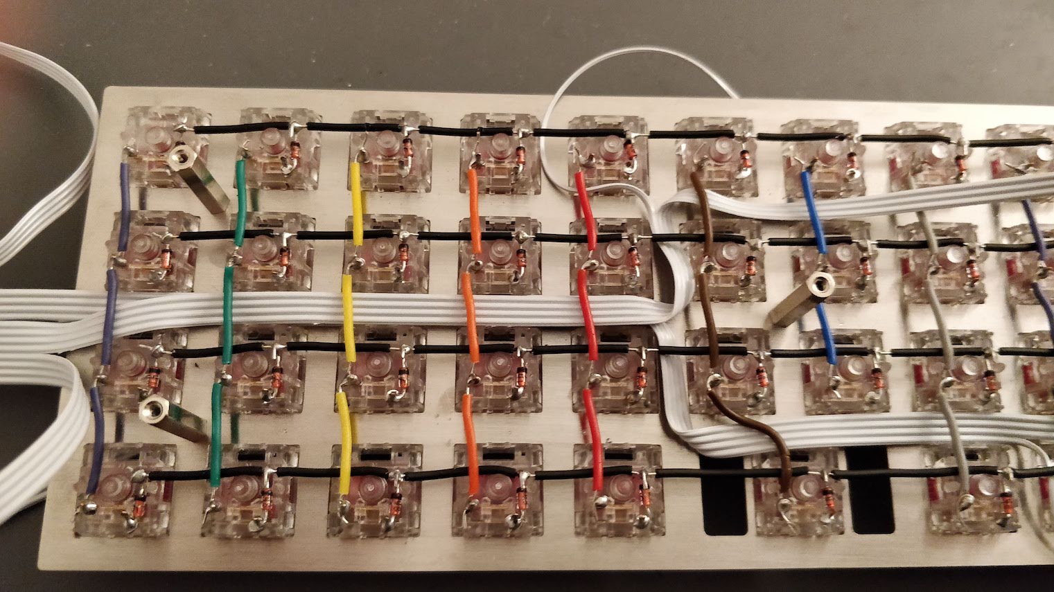
As you can see in the picture, the ribbons turn around the brass spacers. I started routing from the middle lane which was free of spacers until the middle of the plate, then move up or down to access the needed columns.
One thing I didn’t plan very well was that I wanted the controller and its USB port to be on the left of the keyboard. But I did the routing from the left when the keyboard was on the front, so in the end the controller happens to be on the right side. Unfortunately it was to late to change it when I noticed it.
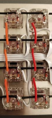
To connect the conductors to the matrix columns, I splitted the ribbon in individual connectors and routed them each to one switch:
Then it is a matter of cutting the conductor to the right length and remove the insulator. Usually it is not possible to use the wire stripper because it requires a large distance between the cut position and the end of the cable which is not possible when the conductor comes from the plate. I had to remove the insulator using a sharp knife and my nails.
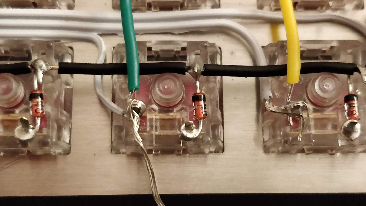
To solder the conductors on the columns, I did a loop with the copper conductors around an existing solder junction, then used the solder iron to heat that existing solder. The loop was incorporated into the existing junction solder easily:
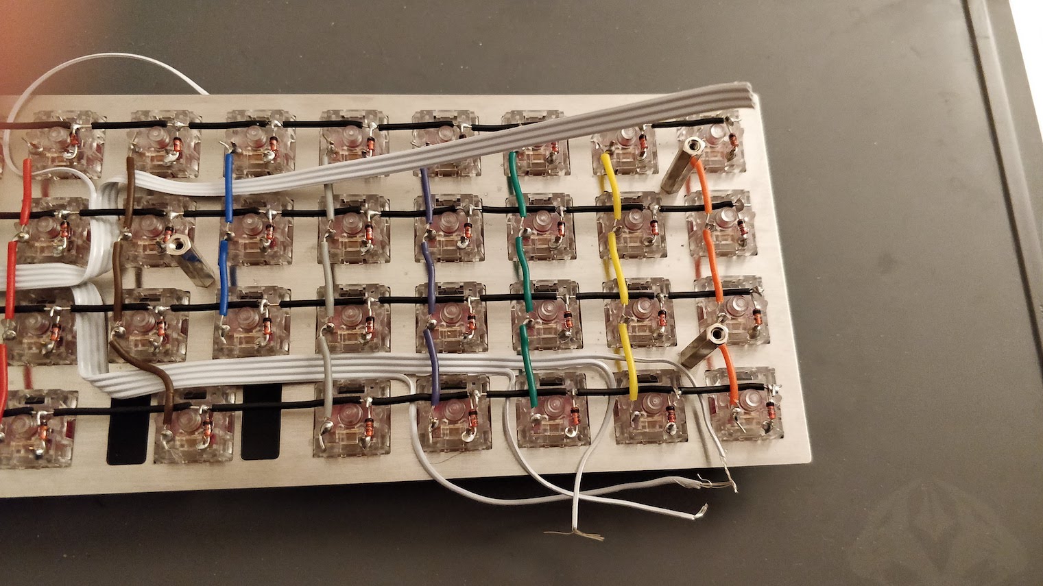
Since we have 12 columns, I decided to route the first 4 conductors ribbon to the column 1 to 4 (the right ones on the back), the second ribbon to the middle ones (5 to 8), and the last column ribbons on the 8 to 12 columns. To balance a bit the routing, the first ribbons connect to the bottom row, the second one to the top row:
The very next step is to route the last 4 conductors ribbon to the rows. The simples solution was to split the 4 conductors ribbon into 2 parts, one going up and one going down. Then solder the wires to the rows on the same column.
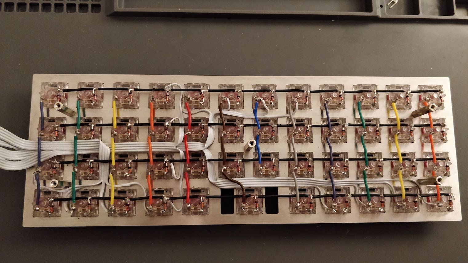
And the final routing result:
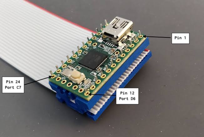
Soldering the controller
The first step is to crimple the DIP support on the ribbon cable. To help aligning the 16 conductors ribbon, I kept the unused 8 conductors part (this way the ribbon can’t move while closing the support).
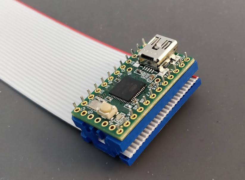
To prevent any electric short between the controller and the switches, the controller is placed upside down, so the support pins are facing down in usual conditions (so the pins are facing up when the keyboard is reversed as in the picture).
Before soldering the controller to the support, I used the multimeter to make sure all the support pins are correctly connected to the matrix. To do that place the black electrode of the multimeter to one of the pin and check it is connected to the correct column or row.
At the same time note which pin is connected to which column or row, as we’ll have to use this information for the firmware:
If you follow exactly this tutorial, you’ll end up with this table for the rows:
| row | pin | port |
|---|---|---|
| 1 | 23 | C6 |
| 2 | 11 | D7 |
| 3 | 24 | D7 |
| 4 | 12 | D6 |
And this one for the columns:
| Column | pin | port |
|---|---|---|
| 1 | 19 | D0 |
| 2 | 7 | F7 |
| 3 | 20 | D1 |
| 4 | 8 | B6 |
| 5 | 22 | D3 |
| 6 | 9 | B5 |
| 7 | 21 | D2 |
| 8 | 10 | B4 |
| 9 | 9 | F6 |
| 10 | 18 | B7 |
| 11 | 17 | B3 |
| 12 | 6 | F5 |
Then solder the Teensy controller. It’s not easy as the Teensy PCB pads are very small, so better use a magnifying glass and a very small solder diameter (0.6mm for instance).
Programming the controller
To program the controller we’ll use QMK. This is an open source keyboard firmware forked and enhanced from TMK. It supports a miriad of custom keyboards and MCU (including various ATmega and ARM micro-controllers).
First, let’s clone the project:
git clone git@github.com:qmk/qmk_firmware.git
cd qmk_firmware
Then install the ATmega toolchain to be able to build the firmware for our keyboard. It’s very easy with the install process:
./util/qmk_install.sh
On macos it requires Homebrew.
Once done, check that you can compile a firmware, for instance the default GH60 keymap (a very well known 60% PCB):
% make gh60:default
QMK Firmware 0.6.193
Making gh60 with keymap default

avr-gcc (GCC) 7.3.0
Copyright (C) 2017 Free Software Foundation, Inc.
This is free software; see the source for copying conditions.  There is NO
warranty; not even for MERCHANTABILITY or FITNESS FOR A PARTICULAR PURPOSE.

Compiling: keyboards/gh60/gh60.c                                                                    [OK]
Compiling: keyboards/gh60/keymaps/default/keymap.c                                                  [OK]
Compiling: quantum/quantum.c                                                                        [OK]
Compiling: quantum/keymap_common.c                                                                  [OK]
Compiling: quantum/keycode_config.c                                                                 [OK]
Compiling: quantum/matrix.c                                                                         [OK]
...
Compiling: lib/lufa/LUFA/Drivers/USB/Core/USBTask.c                                                 [OK]
Linking: .build/gh60_default.elf                                                                    [OK]
Creating load file for flashing: .build/gh60_default.hex                                            [OK]
Copying gh60_default.hex to qmk_firmware folder                                                     [OK]
Checking file size of gh60_default.hex                                                              [OK]
 * The firmware size is fine - 16926/28672 (11746 bytes free)
You should obtain the gh60_default.hex file. You can remove it, we won’t use it.
QMK supports many keyboards and many layouts (called keymaps in QMK) for each keyboard. A keyboard is defined by a directory in the keyboards/ folder, and each keymap is also a directory in the keymaps/ folder of a keyboard. To build such keymap, one need to use the make <keyboard>:<keymap> command.
The make command produces a hex file that can be flashed on the controller with QMK Toolbox, which is the recommended method. We can flash from the command line if we know the controller bootloader type, but QMK Toolbox is able to autodetect the correct bootloader, check the file size and so on. QMK Toolbox also acts as a console for the controller allowing to see debug statements.
For the Teensy, we’ll use the “halfkay” bootloader. One advantage of the Teensy compared to the Pro Micro controller (which we could have used), is that the bootloader is very forgiving: for instance a Pro Micro can be bricked if we flash a firmware that is too large for it.
Let’s implement our own Planck layout. The very first step is to create a new kind of keyboard in the handwired/ keyboard folder. Since it is a Planck keyboard, let’s create a planck folder in which we need to add the following files:
- a
keymaps/folder (in which we’ll create our owndefaultkeymap) - a
rules.mkmakefile which contains our keyboard definition and QMK features enabled - a
config.hwhich defines how our matrix is connected to the controller ports - a
planck.candplanck.hwhich only defines the keymap macro in our case
You can find all the files in my QMK Handwired Planck branch.
Here’s a condensed version of my config.h:
/* key matrix size */
#define MATRIX_ROWS 4
#define MATRIX_COLS 12

/* Our handwired pin-out */
#define MATRIX_ROW_PINS { C6, D7, C7, D6 }
#define MATRIX_COL_PINS { D0, F7, D1, B6, D3, B5, D2, B4, F6, B7, B3, F5 }
#define UNUSED_PINS { B0, B1, B2, F0, F1, F4, D4, D5, E6 }

/* COL2ROW or ROW2COL */
#define DIODE_DIRECTION COL2ROW
We defined here that the matrix is 4x12, and the ports of the rows and columns (in increasing order). Also, we tell QMK that we hooked the diodes between the columns and the rows.
In rules.mk, we tell QMK everything about the used controller:
# This is a teensy 2.0
BOOTLOADER = halfkay
# running this MCU
MCU = atmega32u4
# Processor frequency.
F_CPU = 16000000
# Target architecture (see library "Board Types" documentation).
ARCH = AVR8
# Input clock frequency.
F_USB = $(F_CPU)
# Interrupt driven control endpoint task(+60)
OPT_DEFS += -DINTERRUPT_CONTROL_ENDPOINT
# Boot Section Size in *bytes*
#   Teensy halfKay   512
OPT_DEFS += -DBOOTLOADER_SIZE=512
# Build Options
BOOTMAGIC_ENABLE = no       # Virtual DIP switch configuration(+1000)
MOUSEKEY_ENABLE = no        # Mouse keys(+4700)
EXTRAKEY_ENABLE = yes       # Audio control and System control(+450)
CONSOLE_ENABLE = yes        # Console for debug(+400)
COMMAND_ENABLE = yes        # Commands for debug and configuration
NKRO_ENABLE = no            # Nkey Rollover
BACKLIGHT_ENABLE = no       # There are no leds
MIDI_ENABLE = no            # No MIDI controls
AUDIO_ENABLE = no           # We don't have audio
UNICODE_ENABLE = no         # Unicode
BLUETOOTH_ENABLE = no       # We don't have BT
RGBLIGHT_ENABLE = no        # We don't have underglow
I then created the default keymap. Since this is a Planck replica, I copied over the default Planck keymap of the MIT (2u space) layout. A keymap is a folder in the keymaps/ folder.
Usually the layout is described in the keymap.c file.
This keymap is a 3 layers keymap (base, raise, lower). The base layer can be either qwerty (the default), colemak or dvorak.
A layer is a 2D array representing the keycode associated with a matrix switch. A keymap is an array of layouts (see the keymaps symbol in the keymap.c), one per layer.
The keyboard can be in only one layer at a time, and can be programmed to switch to a given layer with a key combination as explained below.
Here’s for example the keymap of the base qwerty layer of my Planck handwired keyboard:
const uint16_t PROGMEM keymaps[][MATRIX_ROWS][MATRIX_COLS] = {
/* Qwerty
 * ,-----------------------------------------------------------------------------------.
 * | Tab  |   Q  |   W  |   E  |   R  |   T  |   Y  |   U  |   I  |   O  |   P  | Bksp |
 * |------+------+------+------+------+-------------+------+------+------+------+------|
 * | Esc  |   A  |   S  |   D  |   F  |   G  |   H  |   J  |   K  |   L  |   ;  |  '   |
 * |------+------+------+------+------+------|------+------+------+------+------+------|
 * | Shift|   Z  |   X  |   C  |   V  |   B  |   N  |   M  |   ,  |   .  |   /  |Enter |
 * |------+------+------+------+------+------+------+------+------+------+------+------|
 * | Brite| Ctrl | Alt  | GUI  |Lower |    Space    |Raise | Left | Down |  Up  |Right |
 * `-----------------------------------------------------------------------------------'
 */
[_QWERTY] = LAYOUT_planck_grid(
    KC_TAB,  KC_Q,    KC_W,    KC_E,    KC_R,    KC_T,    KC_Y,    KC_U,    KC_I,    KC_O,    KC_P,    KC_BSPC,
    KC_ESC,  KC_A,    KC_S,    KC_D,    KC_F,    KC_G,    KC_H,    KC_J,    KC_K,    KC_L,    KC_SCLN, KC_QUOT,
    KC_LSFT, KC_Z,    KC_X,    KC_C,    KC_V,    KC_B,    KC_N,    KC_M,    KC_COMM, KC_DOT,  KC_SLSH, KC_ENT ,
    BACKLIT, KC_LCTL, KC_LALT, KC_LGUI, LOWER,   KC_SPC,  KC_SPC,  RAISE,   KC_LEFT, KC_DOWN, KC_UP,   KC_RGHT
),
...
}
This corresponds to this layout:
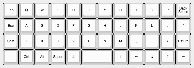
All the people I showed the keyboard asked my why the Esc key is placed below the Tab key. I’m assuming that the original Planck layout has been built this way to enhance the VIM experience. This way the Esc key is on the homerow and can be reached without moving the left hand.
The LAYOUT_planck_grid macro has been defined in our planck.h file. It just maps a keycode to a spot in the layer array representing the matrix.
Notice the two RAISE and LOWER special keycodes. They are layer keycodes defined like this:
#define LOWER MO(_LOWER)
#define RAISE MO(_RAISE)
The MO(layer) macro allows to temporarily activate the given layer when the key is pressed.
The _LOWER and _RAISE layers are defined like this:
...
/* Lower
 * ,-----------------------------------------------------------------------------------.
 * |   ~  |   !  |   @  |   #  |   $  |   %  |   ^  |   &  |   *  |   (  |   )  | Bksp |
 * |------+------+------+------+------+-------------+------+------+------+------+------|
 * | Del  |  F1  |  F2  |  F3  |  F4  |  F5  |  F6  |   _  |   +  |   {  |   }  |  |   |
 * |------+------+------+------+------+------|------+------+------+------+------+------|
 * |      |  F7  |  F8  |  F9  |  F10 |  F11 |  F12 |ISO ~ |ISO | | Home | End  |      |
 * |------+------+------+------+------+------+------+------+------+------+------+------|
 * |      |      |      |      |      |             |      | Next | Vol- | Vol+ | Play |
 * `-----------------------------------------------------------------------------------'
 */
[_LOWER] = LAYOUT_planck_grid(
    KC_TILD, KC_EXLM, KC_AT,   KC_HASH, KC_DLR,  KC_PERC, KC_CIRC, KC_AMPR,    KC_ASTR,    KC_LPRN, KC_RPRN, KC_BSPC,
    KC_DEL,  KC_F1,   KC_F2,   KC_F3,   KC_F4,   KC_F5,   KC_F6,   KC_UNDS,    KC_PLUS,    KC_LCBR, KC_RCBR, KC_PIPE,
    _______, KC_F7,   KC_F8,   KC_F9,   KC_F10,  KC_F11,  KC_F12,  S(KC_NUHS), S(KC_NUBS), KC_HOME, KC_END,  _______,
    _______, _______, _______, _______, _______, _______, _______, _______,    KC_MNXT,    KC_VOLD, KC_VOLU, KC_MPLY
),

/* Raise
 * ,-----------------------------------------------------------------------------------.
 * |   `  |   1  |   2  |   3  |   4  |   5  |   6  |   7  |   8  |   9  |   0  | Bksp |
 * |------+------+------+------+------+-------------+------+------+------+------+------|
 * | Del  |  F1  |  F2  |  F3  |  F4  |  F5  |  F6  |   -  |   =  |   [  |   ]  |  \   |
 * |------+------+------+------+------+------|------+------+------+------+------+------|
 * |      |  F7  |  F8  |  F9  |  F10 |  F11 |  F12 |ISO # |ISO / |Pg Up |Pg Dn |      |
 * |------+------+------+------+------+------+------+------+------+------+------+------|
 * |      |      |      |      |      |             |      | Next | Vol- | Vol+ | Play |
 * `-----------------------------------------------------------------------------------'
 */
[_RAISE] = LAYOUT_planck_grid(
    KC_GRV,  KC_1,    KC_2,    KC_3,    KC_4,    KC_5,    KC_6,    KC_7,    KC_8,    KC_9,    KC_0,    KC_BSPC,
    KC_DEL,  KC_F1,   KC_F2,   KC_F3,   KC_F4,   KC_F5,   KC_F6,   KC_MINS, KC_EQL,  KC_LBRC, KC_RBRC, KC_BSLS,
    _______, KC_F7,   KC_F8,   KC_F9,   KC_F10,  KC_F11,  KC_F12,  KC_NUHS, KC_NUBS, KC_PGUP, KC_PGDN, _______,
    _______, _______, _______, _______, _______, _______, _______, _______, KC_MNXT, KC_VOLD, KC_VOLU, KC_MPLY
),
...
Since on a 40% keyboard we can’t have access to the numbers, function keys, and most of the symbols, those are placed on a different layer than the regular direct access keys. The two raise/lower keys can be actionned by the left and right thumb while at the same time pressing another key to obtain the number or symbol. This is very efficient.
The _______ is an alias for KC_TRANS which means that this key isn’t defined in this layer. When pressing this key while being in this layer, the keycode that will be emited is the first one to not be KC_TRANS in the layer stack. That means that Enter for instance is still Enter in any of the RAISE or LOWER layer.
The rest of the keymap.c file contain special code that overrides the default QMK behavior.
In QMK, a keyboard can override some functionalities, and a keymap can override the keyboard override.
For instance we overrode the process_record function by defining the process_record_user function in our keymap. This is a function which is called each time a key event happens (a key pressed or released). In our case, this is used to switch to a different base layer when going to the ADJUST layer and pressing a base layer key (for instance it is K to switch to colemak). The ADJUST layer is obtained by pressing at the same time the LOWER and RAISE keys.
We also overrode layer_state_set_user to make the LOWER + RAISE = ADJUST layer switching work. The layer_state_set_user function is called whenever QMK is switching to another layer, giving a chance to modify the target layer. We used update_tri_layer_state to return ADJUST when we switched to both LOWER and RAISE.
Now let’s build our firmware:
% make handwired/planck:default
QMK Firmware 0.6.193
Making handwired/planck with keymap default

avr-gcc (GCC) 7.3.0
Copyright (C) 2017 Free Software Foundation, Inc.
This is free software; see the source for copying conditions.  There is NO
warranty; not even for MERCHANTABILITY or FITNESS FOR A PARTICULAR PURPOSE.

Compiling: keyboards/handwired/planck/planck.c                                                      [OK]
Compiling: keyboards/handwired/planck/keymaps/default/keymap.c                                      [OK]
Compiling: quantum/quantum.c                                                                        [OK]
Compiling: quantum/keymap_common.c                                                                  [OK]
Compiling: quantum/keycode_config.c                                                                 [OK]
Compiling: quantum/matrix.c                                                                         [OK]
Compiling: tmk_core/common/host.c                                                                   [OK]
Compiling: tmk_core/common/keyboard.c                                                               [OK]
Compiling: tmk_core/common/action.c                                                                 [OK]
Compiling: tmk_core/common/action_tapping.c                                                         [OK]
Compiling: tmk_core/common/action_macro.c                                                           [OK]
Compiling: tmk_core/common/action_layer.c                                                           [OK]
Compiling: tmk_core/common/action_util.c                                                            [OK]
Compiling: tmk_core/common/print.c                                                                  [OK]
Compiling: tmk_core/common/debug.c                                                                  [OK]
Compiling: tmk_core/common/util.c                                                                   [OK]
Compiling: tmk_core/common/eeconfig.c                                                               [OK]
Compiling: tmk_core/common/report.c                                                                 [OK]
Compiling: tmk_core/common/avr/suspend.c                                                            [OK]
Compiling: tmk_core/common/avr/timer.c                                                              [OK]
Compiling: tmk_core/common/avr/bootloader.c                                                         [OK]
Assembling: tmk_core/common/avr/xprintf.S                                                           [OK]
Compiling: tmk_core/common/magic.c                                                                  [OK]
Compiling: tmk_core/common/command.c                                                                [OK]
Compiling: tmk_core/protocol/lufa/lufa.c                                                            [OK]
Compiling: tmk_core/protocol/usb_descriptor.c                                                       [OK]
Compiling: tmk_core/protocol/lufa/outputselect.c                                                    [OK]
Compiling: lib/lufa/LUFA/Drivers/USB/Class/Common/HIDParser.c                                       [OK]
Compiling: lib/lufa/LUFA/Drivers/USB/Core/AVR8/Device_AVR8.c                                        [OK]
Compiling: lib/lufa/LUFA/Drivers/USB/Core/AVR8/EndpointStream_AVR8.c                                [OK]
Compiling: lib/lufa/LUFA/Drivers/USB/Core/AVR8/Endpoint_AVR8.c                                      [OK]
Compiling: lib/lufa/LUFA/Drivers/USB/Core/AVR8/Host_AVR8.c                                          [OK]
Compiling: lib/lufa/LUFA/Drivers/USB/Core/AVR8/PipeStream_AVR8.c                                    [OK]
Compiling: lib/lufa/LUFA/Drivers/USB/Core/AVR8/Pipe_AVR8.c                                          [OK]
Compiling: lib/lufa/LUFA/Drivers/USB/Core/AVR8/USBController_AVR8.c                                 [OK]
Compiling: lib/lufa/LUFA/Drivers/USB/Core/AVR8/USBInterrupt_AVR8.c                                  [OK]
Compiling: lib/lufa/LUFA/Drivers/USB/Core/ConfigDescriptors.c                                       [OK]
Compiling: lib/lufa/LUFA/Drivers/USB/Core/DeviceStandardReq.c                                       [OK]
Compiling: lib/lufa/LUFA/Drivers/USB/Core/Events.c                                                  [OK]
Compiling: lib/lufa/LUFA/Drivers/USB/Core/HostStandardReq.c                                         [OK]
Compiling: lib/lufa/LUFA/Drivers/USB/Core/USBTask.c                                                 [OK]
Linking: .build/handwired_planck_default.elf                                                        [OK]
Creating load file for flashing: .build/handwired_planck_default.hex                                [OK]
Copying handwired_planck_default.hex to qmk_firmware folder                                         [OK]
Checking file size of handwired_planck_default.hex                                                  [OK]
 * The firmware size is fine - 17618/32256 (14638 bytes free)
Our firmware is in the handwired_planck_default.hex file.
To flash it:
- Connect the Teensy to the computer
- Open QMK Toolbox
- Press the Teensy reset button
- QMK Toolbox will notice a Teensy is connected by displaying
*** Halfkay device connected - Load the firmware
- Choose the
ATMega32U4microcontroller - Press the flash button
You should see something like this:
*** Halfkay device connected
*** Attempting to flash, please don't remove device
>>> teensy_loader_cli -mmcu=atmega32u4 /Users/brice/devl/qmk_firmware/handwired_planck_default.hex -v
    Teensy Loader, Command Line, Version 2.1
    Read "handwired_planck_default.hex": 17618 bytes, 54.6% usage
    Found HalfKay Bootloader
    Programming..........................................................................................................................................
    Booting
*** Halfkay device disconnected
*** masterzen - Planck connected -- 0xFEED:0x6060
At this point your computer should recognize that a new keyboard has been connected. If you press any switches it should produce a letter.
You can now test the keyboard and the keymap with the Keyboard Tester.
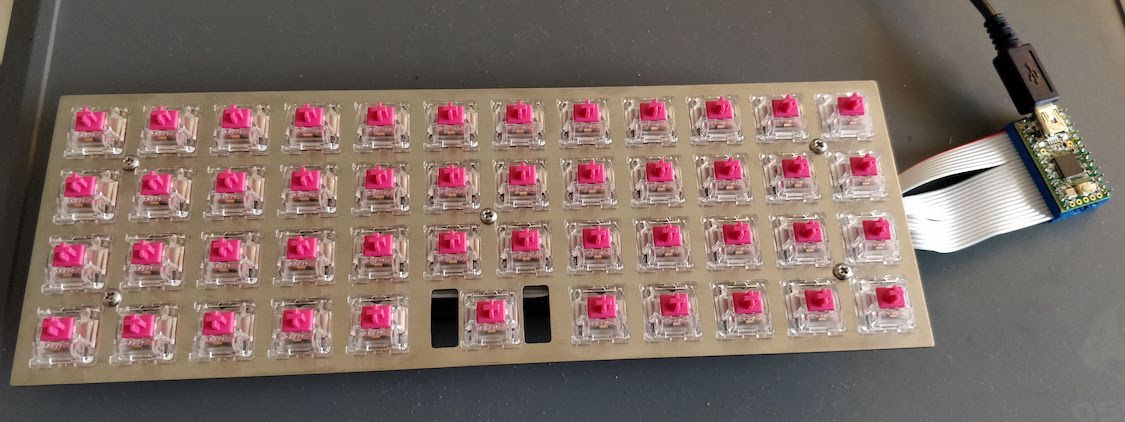
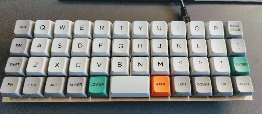
Adding keycaps
It can be hard to find nice 40% ortho keycaps. I used the MDA Big Bang set. It’s a nice, smooth (and not that expensive) thick PBT keyset with dye-sub legends that covers a wide range of ortholinear keyboards, including the Planck.
The MDA (also called MIX or EDRUG) profile is a newer key profile that we could call the little brother of the SA profile. It’s less sculpted than SA, but still more than the other profiles.
Here’s how it looks on this handwired Planck:
What’s coming next
I haven’t had the time to work again on the keyboard, but I want to make it a bit slimmer (it has currently a height of 2cm not including keycaps and switches), and add a transparent bottom plate with small rubber feets.
I plan the bottom plate to be a transparent plexiglass plate (so that we can see the matrix), cut at the size of the metal switch plate. The complex part will be to correctly align the holes for the brass spacer screws along with making sure the hole head fits inside the plate.
To reduce the keyboard height, I will have to carve a small part of the bottom plate so that a small part of the teensy height can fit inside.
If possible, I’d like to build a full case made of plexiglass. I need to design it properly and find the correct tools to do that.
This will probably be the part 3 of this series!
Comments